

Quick Answer
A basic magnetic lock wiring diagram connects a DC power supply to the maglock through an access-control relay. Because a conventional maglock is fail-safe, it stays locked while powered and releases when the circuit cuts power. The reader or keypad tells the controller when access is authorized, while exit and emergency-release devices provide additional ways to release the lock.
What Does a Basic Magnetic Lock Wiring Diagram Include?
A basic magnetic lock circuit includes the following things:
- A compatible DC power supply
- A maglock
- A relay or controller (to determine when power reaches the lock)
A keypad or reader, along with release devices like a request-to-exit sensor or an exit button, can then be added by an access-control system.
The maglock receives continuous DC power while the door is secured. When the system authorizes entry, the relay changes state and interrupts power to the magnet. The magnetic bond then releases, allowing the door to open.
Readers and keypads have a different role. They read the credentials and send information to the controller rather than supplying the magnetic holding force themselves.
For a closer look at the physical setup, see our guide on how to install a magnetic door lock.
How Do You Connect a Maglock to the Power Supply?
First, identify the voltage that is required by the specific lock. Don’t assume that two similar-looking maglocks rely on the same electrical setup.
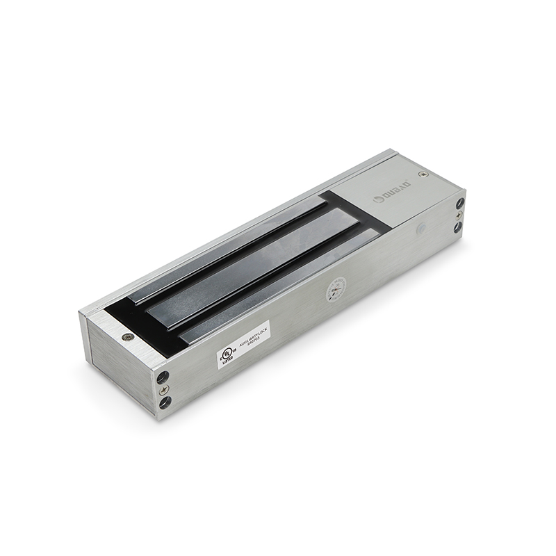
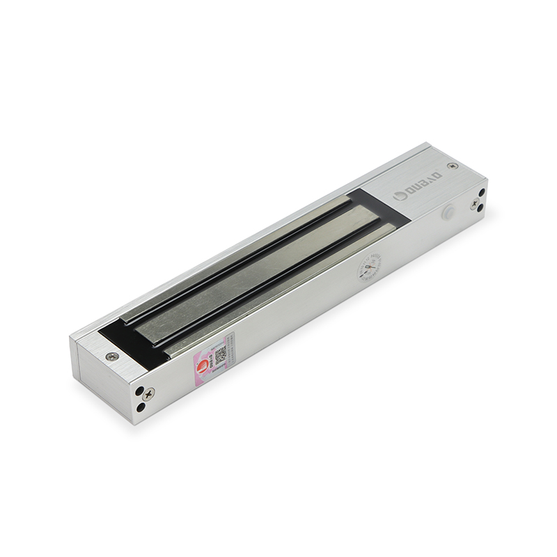
For instance, 12VDC is used by OUBAO’s OB280 Series, with 24VDC offered on request. If you consider the OB500 Series, it supports 24VDC or 12VDC and draws 230mA at 24V or 450mA at 12V. As both types of locks are fail-safe, removing power releases their locking mechanism.
The maglock receives DC power from the power supply via the relay or controller in a typical access-control setup. When the door needs to unlock, the relay changes state and interrupts power to the lock. Make sure the electromagnetic lock power supply matches the voltage specified for the model and delivers enough capacity for the connected load. Long cable runs can also cause the voltage to drop (especially when undersized wiring is used), so check that the lock still receives the voltage specified for the model.
If you’re comparing hardware for a project, OUBAO is a magnetic lock manufacturer offering models for different access-control applications.
- Holding Force500kg (1200lbs)
- MaterialReinforced high-strength aluminum alloy
- CertificationsUL Listed, CE, FCC, RoHS, REACH
What Do NO, NC, and COM Mean in Maglock Wiring?
A maglock wiring diagram typically shows three relay labels: NC, NO, and COM. These are acronyms for normally closed, normally open, and common.
The relay’s NC and COM contacts can be used to control the power circuit for a fail-safe maglock. In the relay’s normal state, the circuit through NC and COM remains closed, allowing power to reach the magnet. When the relay changes state after authorized access, that path opens and interrupts power to the lock.
But those relay terminals must not be confused with status contacts built into a lock. Some magnetic locks provide separate signal outputs for monitoring rather than switching the lock’s main power circuit.
OUBAO’s OB280 is one example of a signal-output model, while its OB500 lock is listed with NO/COM/NC signal output. If you’re wiring either model, follow its specific wiring documentation rather than assuming these contacts serve the same purpose as the controller relay.
- Holding Force280kg (600lbs)
- TypeStandard-duty magnetic lock
- ApplicationEveryday commercial applications
Where Do the Reader and Exit Button Fit?
The keypad or reader connects to the access-control system and handles entry. When a valid code, card, or other credential is presented to it, the system tells the controller to release the magnetic lock.
The request-to-exit device or exit button manages the release from inside the door. Depending on the wiring arrangement, activating it either signals the access-control system to release the lock or directly interrupts power to the lock.
However, the way these devices are wired can vary between access-control systems. That’s why it’s better to follow the instructions given by the manufacturer. Copying connections from a generic magnetic lock wiring diagram is not recommended. You should also know that egress requirements may affect how the exit device has to release the lock.
Our guide to how magnetic locks work explains what happens when power reaches or is removed from the magnet.
How Does Fire-Alarm Integration Affect Magnetic Lock Wiring?
No one electromagnetic lock wiring diagram applies to every fire-alarm setup.
But some electromagnetic-locking arrangements are required to release when an automatic sprinkler system or fire alarm activates. Requirements can vary based on the arrangement, with the release method, opening, jurisdiction, and adopted code all determining what applies.
As such, calling a lock “fail-safe” doesn’t make the fire-alarm wiring compliant by default. The term only describes the function that the lock performs when the power is removed. The whole system still needs to be designed in order to ensure any critical emergency-release functions work correctly.
What Should You Check Before Powering the System?
Before switching on the system, confirm the lock’s specified voltage, maglock power supply capacity, wiring connections, and polarity where applicable. Check that the magnet receives the correct voltage at the lock and that the door hardware is properly aligned.
Then test every intended release method. Verify that authorized entry releases the magnet, exit controls work as designed, and removing power releases the fail-safe lock. Test any required emergency-release functions as part of the complete system too.
Most importantly, use the wiring instructions for the exact model you’re installing. A generic maglock wiring diagram helps you understand the circuit, but it should never replace the manufacturer’s model-specific instructions or the electrical, access-control, egress, and fire-safety requirements for the opening.